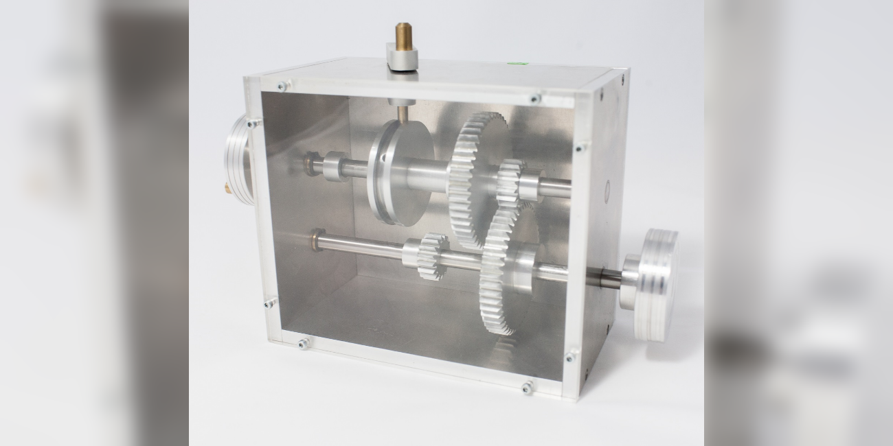

Machine Elements and Mechatronics II

Lecture: Machine Elements and Mechatronics II

Here you can find information about the lecture: Machine Elements and Mechatronics II

MM II – Machine Elements and Mechatronics II

Lecturer Type and scope of the lecture
Prof. Dr.-Ing. Eckhard Kirchner 8 hours a week (lecture + exercise)
Lecture Exercise
Lecture in summer semester
Tu 09:50 – 11:30 in L402/1+2
Fr 08:00 – 09:40 in L402/1+2
distribution for the exercise groups is announced the first lectures
Language of lecture and exam is German.
Contact
For organisational questions regarding the lecture, lecture hall and group exercise or examination in MM II, please contact only:

Information about the oral supplementary examination MM II

The oral supplementary examination lasts approximately 75 minutes (including the announcement of grades) and consists of two parts:

  • First, candidates are required to constructively solve a drive technology problem and present their solution as a hand-drawn sketch on A4 paper. The scope of the task is approximately 30% of a typical design task from an exam. No aids other than drawing tools are permitted.
  • In the oral part, the constructive solution and any errors are first discussed and analysed. This is followed by an examination of your basic understanding of the subject ‘Machine Elements and Mechatronics II’, with the entire content of the course being relevant to the examination. However, the focus is on the essential interrelationships and the basic approach to the design of machine elements and the fundamental calculation equations required for this – simply reciting equations is not necessary! Furthermore, you are expected to know and be able to interpret relevant influencing factors and parameters. A script including errata and all lecture slides will be provided on site.

We wish you much success in your preparation.

News

News can be found at the institute's news.

Contents

The second part of the lecture “Machine Elements and Mechatronics” deals with the mechanical machine elements. It starts with the design methods for components in general and their dimensioning under stationary and unsteady use. After that, specific mechanical machine elements are looked at, starting with simple elements. Based on connections, students deal with suspensions, dampers, couplings, bearings and keyways as well as seals.

Moodle

Information, lecture notes and supplementary materials are available on the e-learning platform Moodle (Moodle_TU_Darmstadt) of the course “Machine elements II”.

English language group exercises in the summer term

Group exercises with English language supervision are offered in the next summer term. English-speaking students who are enrolled in the conditional course for masters are strongly advised to attend these group exercises and not to take the written exam until they have completed the exercises. Especially the design part of the exam requires dedicated training, you should organize yourself in learning teams and learn from each other’s creative ideas and mistakes.

English language exam consultation hours

In the summer semester as well as in the winter semester there will be four exam consultation hours before the exam held online. There are dedicated rooms for major topics with Q&A mainly in German, a specially dedicated virtual room will be added for the English speaking students.

Additional English literature

  • Bhandari, V. B. (2017). Design of Machine Elements. McGraw-Hill Education (India)
  • Childs, P. R. N. (2018). Mechanical Design Engineering Handbook
  • Jiang, W. (2019). Analysis and design of machine elements (Wei Jiang, Ed.). John Wiley & Sons
  • Mott, R. L. (2013). Machine elements in mechanical design
  • Schmid, S. R., Hamrock, B. J., & Jacobson, B. O. (2014). Fundamentals of Machine Elements, Third Edition. Taylor & Francis

Additional documents and links

The collection of links is only available for members of the TU Darmstadt. Login with your TU-ID to get access.

Access restricted section: Log in to see this section.

1. Einleitung

2. Festigkeitsnachweise

2.2.1 Duktiles Bauteilverhalten (PDF file) (opens in new tab)

3. Spezifikation von Toleranzen und technischen Oberflächen auf Bauteilebene

3.1 Geometrieabweichungen (PDF file) (opens in new tab)

3.2 Grenzlehren (PDF file) (opens in new tab)

4. Bauteilkontakt

5. Bauteilgestaltung

6. Bauteilverbindungen

6.3.4 Blindnietzange und Blindniete (PDF file) (opens in new tab)

6.3.6 Demonstrator Formschluss (PDF file) (opens in new tab)

6.3.6 Formschlüssige Welle-Nabe-Verbindung (PDF file) (opens in new tab)

6.3.8 Formschlüssige Welle-Nabe-Verbindung (Zahnwellenverbindung) (PDF file) (opens in new tab)

6.4 Toleranz(ausgleichs)hülse (PDF file) (opens in new tab)

6.4.4 Schrumpfscheibe (PDF file) (opens in new tab)

6.4.4 Spannsatz (PDF file) (opens in new tab)

7. Federungen und Dämpfer

7.2.1 Demonstrator Schaltungen von Federn (PDF file) (opens in new tab)

7.2.2 Zweimassenschwungrad (PDF file) (opens in new tab)

7.3.2 Modell Balgfeder (PDF file) (opens in new tab)

7.3.5 Demonstrator Tellerfedern (PDF file) (opens in new tab)

7.5 Modell Feder-Dämpfer-Kombination (PDF file) (opens in new tab)

7.6 Demonstrator Dämpfende Eigenschaften (PDF file) (opens in new tab)

7.6.2 Demonstrator reine Dämpfung (PDF file) (opens in new tab)

7.6.2 Modell progressive Kennlinie (PDF file) (opens in new tab)

8. Schraubenverbindungen

8.3 Verspannte Schraubenverbindungen (PDF file) (opens in new tab)

8.3.3 Krafteinleitungsfaktor (PDF file) (opens in new tab)

8.3 Schraubendehnung (PDF file) (opens in new tab)

8.4 Schraubenmontage Turbolader (kalt) (PDF file) (opens in new tab)

8.4 Schraubenmontage Turbolader (warm) (PDF file) (opens in new tab)

8.5 Versagen einer Schraubenverbindung (PDF file) (opens in new tab)

8.6.4 Schraubensicherungen (PDF file) (opens in new tab)

9. Wälzlager

9.2.2 Verschiedene Wälzlager (PDF file) (opens in new tab)

9.2.4 Verschiedene Käfigbauformen (PDF file) (opens in new tab)

9.3.5 Demonstrator Axiallager (PDF file) (opens in new tab)

9.4.2 Schadensformen (PDF file) (opens in new tab)

9.5 Elemente zur axialen Fixierung (PDF file) (opens in new tab)

9.5 Messung der radialen Lagerluft (PDF file) (opens in new tab)

10. Gleitlager

10.2.1 Faserverbundlagerschale (PDF file) (opens in new tab)

10.2.1 Kunststofflager (PDF file) (opens in new tab)

10.2.1 Trockenlaufscheibe (PDF file) (opens in new tab)

10.2.1 Gleitlagerbuchsen (PDF file) (opens in new tab)

10.2.1 Lagerbuchse mit Schmierstoffdepots (PDF file) (opens in new tab)

10.2.2 SAF-Bremsenlager (PDF file) (opens in new tab)

11. Dichtungen

11 Dynamische Dichtungen (Kolbenring) (PDF file) (opens in new tab)

11 Dynamische Dichtungen (Radialwellendichtring) (PDF file) (opens in new tab)

11 Statische Dichtungen mit Linienkontakt (PDF file) (opens in new tab)

11 Statische Dichtungen (PDF file) (opens in new tab)

12. Kupplungen

12.3.1 Versatzausgleichkupplungen (Bogenzahnkupplung) (PDF file) (opens in new tab)

12.3.1 Versatzausgleichkupplungen (Klauenkupplung) (PDF file) (opens in new tab)

12.3.1 Versatzausgleichkupplungen (Kreuzscheibenkupplung) (PDF file) (opens in new tab)

12.3.1 Versatzausgleichkupplungen (Parallelkurbelkupplung) (PDF file) (opens in new tab)

12.3.2 Gleichlaufgelenkkupplungen (PDF file) (opens in new tab)

12.3.2 Kreuzgelenkkupplungen (PDF file) (opens in new tab)

12.4 Elastische Kupplung (PDF file) (opens in new tab)

12.4 Elastische Kupplungen (Metallbalgkupplung) (PDF file) (opens in new tab)

12.6 Sicherheitskupplung (PDF file) (opens in new tab)

13. Systematik von Getrieben

13.1 Handgetriebe / Handbohrmaschine (PDF file) (opens in new tab)

13.1 Kurvengetriebe / Geteilte Kurbelwelle (PDF file) (opens in new tab)

13.1 Spannungswellengetriebe (PDF file) (opens in new tab)

13.1 Spannungswellengetriebe Harmonic Drive (PDF file) (opens in new tab)

13.1 Zykloidgetriebe (PDF file) (opens in new tab)

13.2.1 Getriebemotor (PDF file) (opens in new tab)

13.2.1 Stirnrad- und Schneckengetriebe (PDF file) (opens in new tab)

13.2.1 Einstufiges Kronradgetriebe (PDF file) (opens in new tab)

13.2.1 Einstufiges Stirnradgetriebe (PDF file) (opens in new tab)

13.2.1 Schneckengetriebe (PDF file) (opens in new tab)

13.2.2 Schaltbares einstufiges Stirnradgetriebe (PDF file) (opens in new tab)

13.2.2 Sechsgang Schaltgetriebe (PDF file) (opens in new tab)

13.2.2 Zweistufiges Stirnradgetriebe (PDF file) (opens in new tab)

13.2.3 Evolventenverzahnung (Zahngeometrie) (PDF file) (opens in new tab)

13.2.3 Evolventenverzahnung (Tangenten) (PDF file) (opens in new tab)

13.2.3 Evolventenverzahnung (Profilverschiebung 1) (PDF file) (opens in new tab)

13.2.3 Evolventenverzahnung (Profilverschiebung 2) (PDF file) (opens in new tab)

13.3.1 Kurvengetriebe (translatorisch) (PDF file) (opens in new tab)

13.3.1 Kurvengetriebe (PDF file) (opens in new tab)

13.3.1 Malteserkreuzgetriebe (PDF file) (opens in new tab)

13.3.3 Ketten- und Riemengetriebe (PDF file) (opens in new tab)

13.3.3 Schaltschieber/Schieberkasten/Hydraulik (PDF file) (opens in new tab)

13.3.5 Dreifach-Keilriemenscheibe (PDF file) (opens in new tab)

13.3.5 Flachriemengetriebe (PDF file) (opens in new tab)

Gestaltung

Blech (PDF file) (opens in new tab)

Drehen (PDF file) (opens in new tab)

Fräsen (PDF file) (opens in new tab)

Gießen (PDF file) (opens in new tab)

Schweißen (PDF file) (opens in new tab)

Contact Persons

Prof. Dr.-Ing. Eckhard Kirchner

Contact

work +49 6151 16-21171

Work L1|01 251
Otto-Berndt-Straße 2
64287 Darmstadt

Patrick Kortenbusch M.Sc.

Working area(s)

Sensing Machine Elements

Contact

work +49 6151 16-21180

Work L1|01 242
Otto-Berndt-Straße 2
64287 Darmstadt